Electric charge moves along conductors, creating a flow called electric current. Putting several conductors together builds an electric circuit. Some conductors allow electric charges to flow more easily than others. How much opposition the conductor offers to the flow of electric charge is called resistance. Resistance is measured in Ohms.
The first circuit below connects a battery to an LED using a resistor to control the flow of current through the LED. This prevents the LED from burning! The battery has an outlet that is negatively charged. The amount of electric charge is measured in Volts. Electric charge flows from that outlet through the circuit until it meets the switch. If the switch is open, the electric charge cannot go through and there is no current in the LED, which is then off. If the switch is closed, the electric charge goes through and lights up the LED.
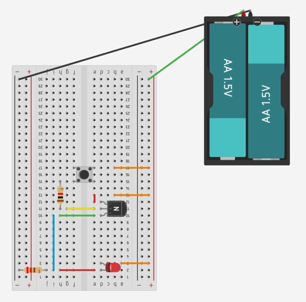
The second circuit above implements a NOT gate using a transistor. This transistor allows current to pass through if the base is positively charged. Thus, we connect the base of the transistor to the positive outlet of the battery with a switch and another resistor to control the flow of current. When the switch is closed, the current flows through the transistor from the negative outlet of the battery to the positive one without going through the LED, which is then off. Otherwise, the current flows through the LED lightning it up. If S represents the switch and L represents the LED, we have L=!S, where ! is a symbol usually used in computer coding to represent not.
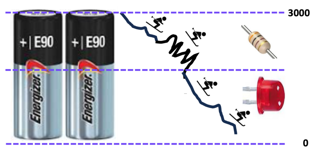
The battery is like a high mountain where skiers start from. The LED is a significant drop in altitude. The resistor is a pack of bumps on the way to control the flow of current, which ends up being constant across the circuit. This is shown in the first picture below. The second picture below shows the diagram for the NOT gate using Tinkercad. The movie below shows the flow of electric charge through the NOT gate using Circuit-js.