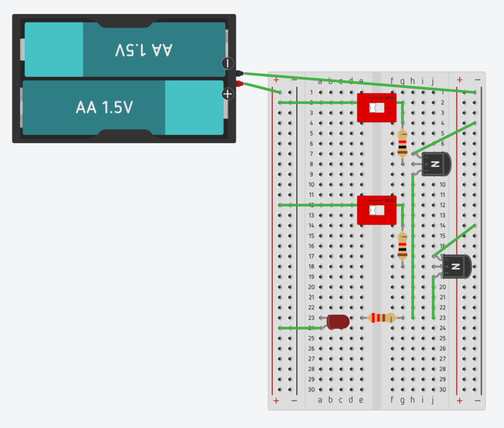
An OR gate lights up the LED when switch 1 is on or when switch 2 is on. We can build this circuit by connecting the transistors in “parallel”. Parallel means that one path is an alternative to another path when paths are “side by side”.
A NOR gate will do the opposite and light up the LED only when both switches are off. The NOR gate is obtained by driving the flow of current through the LED when the OR gate is “open”. That is, the negative outlet of the battery is directly connected to the LED through a resistor, and electric charge chooses this path to flow through when the OR gate does not allow current to flow. When the OR gate is “closed”, the current flows through it because this path offers less resistance than the LED, leaving the LED off. The pictures and videos below show these circuits and the corresponding truth tables.

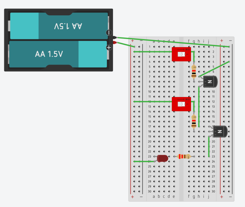
An AND gate lights up the LED when switch 1 is on and when switch 1 is on. We can build this circuit by connecting the transistors in “series”. Series means that there is only one path with conductors in tandem. A NAND gate will do the opposite and shut down the LED only when both switches are on. Using an idea similar to the one employed to design the NOR gate, The NAND gate is obtained by allowing the flow of current through the LED when the AND gate is “open”. When the AND gate is “closed”, the current flows through it, because that’s the path of least resistance, leaving the LED off. The pictures and videos below show these circuits and the truth tables.